Considerations for Solar Car Auxiliary Power
The Bridgestone World Solar Challenge (BWSC) is a 3,000 km drive through the Australia Outback to test the limits of the most efficient solar cars. The electrical systems in any EV are complex, and even more so in a solar-powered one.
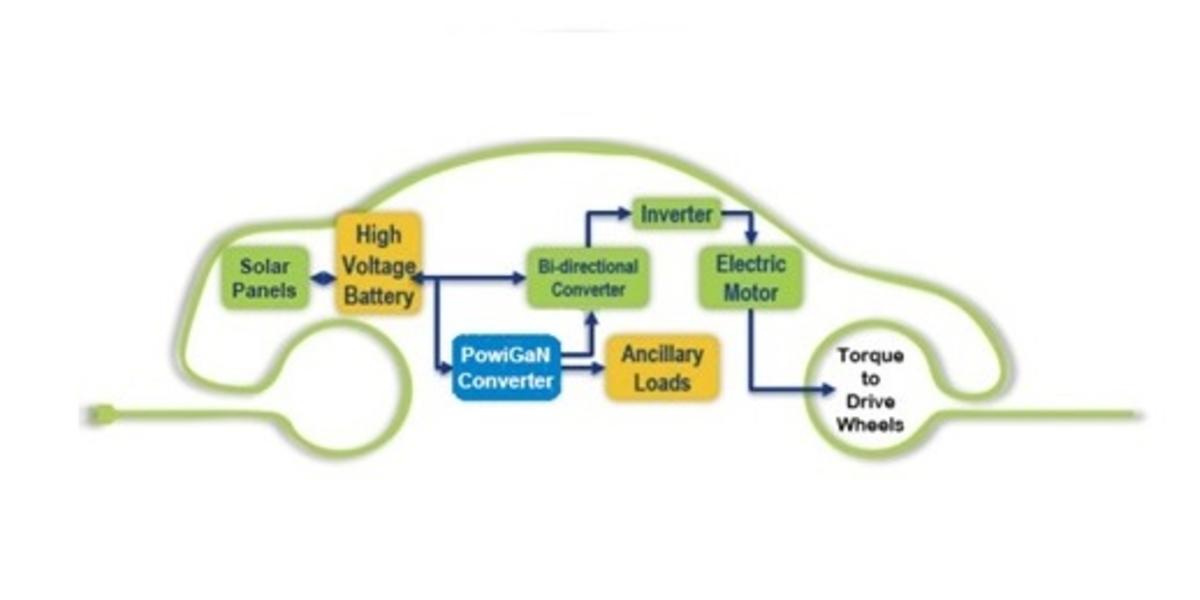
There are two main systems in the vehicle, a high-power circuit to drive the motor(s), and low-power circuits to drive the auxiliary system. High-power components oriented toward propulsion include:
- Solar Panels - Nominally provide enough power to run the drive and auxiliary systems
- High Voltage Battery - Provides power when solar production is insufficient
- Bi-Direction Converter and Motor Controller - Both controls and provides high power from the solar/battery to the inverter
- DC-AC Inverter - Converts DC current to AC current for the drive motor(s)
- Drive Motor(s) - Convert electrical energy to mechanical force in order to propel the vehicle. Also, in many cases, they generate electrical energy during braking and feed that back to the battery
Equally important, though, are the control and safety circuits, along with other ancillary loads, which can include:
- Displays
- Sensors
- Telemetry transmitter/receivers
- Lighting
- Control/safety circuits
Without a reliable source of auxiliary power not only would those displays go dark, but the ramifications would be huge. Because the motor controller also needs auxiliary power for its circuits, the car would literally be dead in its tracks! And dead in your tracks is not something you would want to be in the Australian Outback.
Many considerations for auxiliary power need to be balanced, including efficiency, safety, and reliability. A traditional design, like that found in many electric vehicles on the road today, would use a separate 12/24/48 V batter to provide auxiliary power, with DC-DC step-down (buck) converters as necessary to power the display and other electronics. This arrangement adds both weight, complexity, and additional points of potential failure to the system, none of which are desirable in a vehicle that is supposed to maximize efficiency. There is a better way.
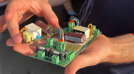
One of the teams making that journey is αCentauri (aka αCe) Solar Race Team from ETH Zurich, who employ a PowiGaN-based InnoSwitch offline switcher IC from Power Integrations to power the control board of the No. 85 race car. αCe was drawn to the PowiGaN InnoSwitch for their auxiliary DC-DC converter because its 750V PowiGaN switch provides protection from any power spikes created in the 400V high voltage side of the converter.
Further, the Fluxlink-enabled flyback circuit maximizes efficiency while simultaneously providing robust isolation without the use of an optocoupler, which reduces the number of components in the feedback circuits, increasing efficiency. And it eliminates several potential points of failure, including the aforementioned optocoupler. PowiGaN and Fluxlink really are gamechangers for this team.
Mr. Green’s Blog is on location cheering for the αCentauri Solar Race Team. Follow #PowiGaNVan on Power Integrations’ official YouTube Channel and LinkedIn Page.
This Mr. Green blog is part of a special series of blogs, vlogs, livestreams and social posts from the #PowiGaNVan as we follow Team αCentauri through the Australian Outback for the Bridgestone World Solar Challenge.


